How to Recap a Vintage Amplifier or Receiver
SAFETY WARNING: HIGH VOLTAGE DANGER Vintage amplifiers and receivers contain lethal voltages. Even when unplugged, large filter capacitors can hold a significant charge for days or weeks. Always discharge power supply capacitors before touching internal circuitry. Consult the service manual for your specific model, or have a qualified technician perform the discharge procedure—correct resistor values and precautions vary by unit and should not be assumed. Never work on a “live” chassis unless you are using an isolation transformer and have extensive experience with high voltage safety protocols. If you are unsure of your ability to safely handle mains voltage, take your unit to a professional technician.
Vintage audio gear from the golden era of the 1970s was built to last, but the laws of chemistry are immutable. The electrolytic capacitors used in legendary units like the Marantz 2270 or the Sansui AU-717 were never intended to function for fifty years. These components rely on a liquid or gel electrolyte that slowly evaporates, leading to increased internal resistance and eventual failure. When people complain that vintage gear sounds “warm” or “veiled,” they are often hearing the sound of dying components rather than the intended sonic signature of the manufacturer.
Recapping is the process of replacing these aged electrolytic capacitors with modern, high quality equivalents. It is one of the most effective ways to restore the transient response, low frequency authority, and overall transparency of a classic receiver. While the task can seem daunting due to the hundreds of components involved, a systematic approach combined with the right tools makes it a manageable project for any dedicated hobbyist. This guide will walk you through the technical requirements and the practical execution of a full recap vintage amplifier project.
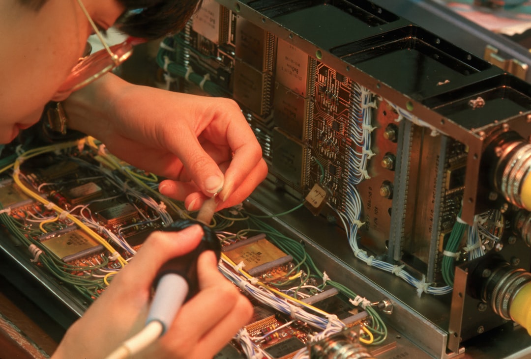
Photo by Community Archives of Belleville and Hastings County on Unsplash
Why You Must Recap Vintage Amplifiers for Longevity
The primary reason to recap vintage amplifier units is the inevitable degradation of electrolytic capacitors. Unlike resistors or transistors, which can often last indefinitely if not overstressed, electrolytic capacitors are chemical devices with a finite lifespan. Over decades, the seal on the capacitor can fail, allowing the electrolyte to dry out. This leads to a rise in Equivalent Series Resistance (ESR). When ESR increases, the capacitor can no longer filter AC ripple effectively or pass signal with transparency. In a power supply circuit, high ESR results in increased hum and instability. In the signal path, it acts as a high pass filter, effectively “choking” your bass response and making the amplifier sound thin or muddy.
Beyond sonic degradation, there is the very real risk of catastrophic failure. In massive powerhouses like the Pioneer SX-1980, the large filter capacitors are responsible for smoothing the massive current required for high wattage output. If one of these “cans” shorts internally, it can take out the power transformer, a part that is often irreplaceable today. Furthermore, certain brands of capacitors from the 1970s, such as the infamous “Sky Blue” Sanyos or certain Elna series, are known to leak corrosive fluid onto the printed circuit board (PCB). This fluid can eat through copper traces and create conductive paths that cause intermittent shorts.
Another factor worth understanding is the improvement in modern component manufacturing. A modern Nichicon or Panasonic capacitor is significantly smaller and more electrically stable than its 1975 equivalent. Modern caps have tighter tolerances and higher temperature ratings (often 105°C compared to the vintage 85°C standard). By replacing the old parts, you are restoring the amp’s performance to within its original design specifications, and modern replacements’ higher temperature ratings can improve long-term reliability. This is particularly true for the power supply section, where lower ESR and higher ripple current ratings in modern caps allow the amplifier to handle complex musical peaks with much greater ease. If you have already followed our guide on how to diagnose hum in a vintage HiFi system, you likely already know that power supply caps are the prime suspects for noise issues.
Essential Tooling and Component Selection
You cannot perform a professional-grade recap with a cheap, non-regulated soldering iron from a hardware store. Vintage PCBs are often made of phenolic resin or early fiberglass, and the copper traces are extremely delicate. Excessive heat will cause the traces to “lift” from the board, turning a simple restoration into a nightmare of jumper wires. A temperature-controlled soldering station such as the Hakko FX-888DX is widely recommended for this type of work because of its exceptional thermal recovery and precise temperature control. Setting your iron to approximately 330°C to 350°C (625°F to 660°F) is usually the “sweet spot” for vintage leaded solder without damaging the pads.
Desoldering is where most beginners fail. Solder braid can work, but it often requires too much dwell time on the pad. As an Amazon Associate, I earn from qualifying purchases. The ENGINEER SS-02 Solder Sucker Desoldering Pump is an essential tool for this job. Its flexible silicone tip allows you to form a vacuum seal directly over the solder joint, pulling the molten solder out in one clean snap. This minimizes the heat exposure to the PCB and leaves the holes clear for the new component leads. Cleanliness is also paramount: keep a bottle of 99% Isopropyl alcohol and a stiff nylon brush nearby to remove old flux and any leaked electrolyte from the board surface before installing new parts.
When it comes to the capacitors themselves, “audio grade” is not just marketing jargon. For signal-path positions (anywhere the music actually travels), many restorers choose Nichicon Muse FG Fine Gold Audio-Grade Electrolytic Capacitors, which are designed for low distortion and a neutral sonic character. For the power supply and protection circuits, high-reliability, low-ESR series such as the Nichicon PW or Panasonic FR are commonly specified—these are rated for long life and high heat, making them well-suited to the “engine room” of the amplifier. Always buy your components from reputable distributors like Mouser or Digi-Key to avoid the counterfeit parts that plague the market. You can find detailed service manuals and parts lists on sites like HifiEngine, which are indispensable for identifying every capacitor in your specific model.
The Step-by-Step Recap Vintage Amplifier Process
Recapping is a marathon, not a sprint. A complex receiver like a Sansui G-8000 can have over 100 electrolytic capacitors spread across half a dozen boards. The key to success is documentation and a methodical “one-by-one” replacement strategy. Never pull all the capacitors out of a board at once. If you get distracted and come back to a bare board, you will likely forget the polarity or the specific values required for each position.
- Obtain the Service Manual: Before you turn a single screw, find the schematic and the parts list for your unit. This will tell you the capacitance (uF) and voltage (V) for every component.
- Map the Boards: Take high-resolution photos of every PCB. Note the orientation of the existing capacitors. While the PCB usually has a “+” or a shaded area for the negative side, vintage silk-screening can occasionally be wrong. Trust your photos and the actual orientation of the factory parts.
- Discharge the Power Supply: Follow the discharge procedure in your unit’s service manual—or consult a qualified technician—to safely bleed the energy from the large filter cans. Verify with a multimeter that the voltage has dropped to near zero before proceeding.
- Work One Board at a Time: Start with the power supply board, as it is usually the most critical. Move then to the power amp stages, the phono preamp, and finally the tone control board.
- Remove the Old Component: Apply a small amount of fresh leaded solder to the joint to improve heat transfer. Use the ENGINEER SS-02 to remove the old solder. Gently rock the capacitor to free the leads and pull it out.
- Prepare the Pad: Clean the area with Isopropyl alcohol. Ensure the holes are clear of any remaining solder.
- Install the New Capacitor: Double-check the polarity. Electrolytic capacitors are polarized: the long lead is positive, and the stripe on the body marks the negative lead. Inserting one backwards will cause it to pop or even explode when the unit is powered on.
- Solder and Trim: Use high-quality 60/40 or 63/37 leaded solder. Form a clean, concave “fillet” around the lead. Trim the excess lead with flush cutters, making sure the “snipped” end doesn’t fly into the circuitry.
- The Dim Bulb Test: Once a board is finished, testing the unit with a “Dim Bulb Tester” is a recommended practice among restorers. This is a simple series circuit with an incandescent light bulb that limits current. If there is a short, the bulb glows brightly, protecting the transistors from damage.
Understanding Capacitor Types and Values
When you begin your recap vintage amplifier journey, you will encounter various types of capacitors beyond the standard electrolytic. It is important to know which ones to replace and which ones to leave alone. Generally, film capacitors (polyester or polypropylene) and ceramic disc capacitors do not “wear out” like electrolytics do. Unless you have a specific reason to suspect failure, or you are performing a high-end sonic “mod,” you should leave these original components in place. The exception is the “Rifa” brand film capacitors often found in the power entry section: these are notorious for cracking and smoking as they age and should be replaced with modern X2-rated safety capacitors.
Regarding values, there are two numbers to watch: Capacitance (measured in microfarads, or uF) and Voltage (V). For the capacitance, you should aim to match the original value exactly, especially in timing circuits or the phono stage where the value affects the RIAA equalization curve. For the large “main filter” capacitors in the power supply, matching the original value is a safe baseline for reliability restoration. Some restorers choose to increase capacitance by 20% to 50% where physical space permits, on the basis that higher capacitance may improve current reserves for bass-heavy material—but this is an optional modification rather than a reliability requirement, and opinions on the audible benefit vary.
Voltage ratings are a different story. The voltage rating on a capacitor is its maximum “ceiling.” You can always use a higher voltage rating than the original, but never lower. If the original was 35V, you can safely use a 50V or 63V replacement. In fact, modern capacitors are so much smaller that a 50V modern cap is often the same size as a 25V vintage cap. Using a higher voltage rating provides a larger safety margin and can sometimes result in lower ESR. The only downside to going significantly higher in voltage (e.g., using a 100V cap where a 10V was) is that the capacitor may never properly “form” its dielectric layer, though this is a subject of much debate among audiophiles.
Troubleshooting and Post-Recap Testing
Even the most careful technician can make a mistake. If you power on your amplifier after a recap and hear a loud hum, see smoke, or the protection relay fails to click, you must immediately cut the power. The most common error is a reversed polarity capacitor. Go back to your reference photos and check every single new component. A single capacitor installed backwards in the protection circuit can prevent the relay from engaging, even if the rest of the amp is perfect.
Another frequent issue is the “solder bridge.” This happens when a small blob of solder connects two adjacent pads that should be separate. This is common on the crowded boards of late-70s gear like the Sansui AU-717. Use a magnifying glass or a jeweler’s loupe to inspect your work. Look for “cold” solder joints as well: these look dull and grainy rather than shiny and smooth. A cold joint can cause intermittent signals or crackling noises. If you find one, simply reflow it with a bit of fresh solder and your iron.
Once the unit is powered on and the relay clicks, your job isn’t quite done. A full recap often changes the internal voltages slightly because the new capacitors are more efficient. You must now check and adjust the “DC Offset” and “Idle Current” (Bias). DC Offset is the amount of direct current present at the speaker terminals: it should be as close to 0mV as possible (ideally under 20mV). Idle current determines how much the output transistors “turn on” at rest. If the bias is too low, you get crossover distortion; if it is too high, the amp will overheat and eventually fail. Your service manual will provide the specific test points and potentiometer adjustments for these settings. This is also the perfect time to ensure your controls are functioning correctly by following our guide on how to clean vintage amp controls and switches.
Frequently Asked Questions
Should I replace the large “Can” filter capacitors?
Replacing the large main filter capacitors is often the most expensive part of a recap, but it is also the most vital for the health of the power transformer. These capacitors handle the most stress and are the most likely to cause catastrophic failure if they short. While some people “re-stuff” the old cans to maintain the vintage look, most restorers choose modern replacements that fit the original clamps. If the new capacitors are smaller, you can use 3D-printed adapters or foam spacers to secure them. Given the high cost of vintage transformers in units like the Pioneer SX-1980, the price of new filter cans is cheap insurance.
Does recapping change the “vintage sound” of the amplifier?
This is a controversial topic in the HiFi community. Some purists argue that the “dry” or “leaky” capacitors contribute to a specific vintage warmth. From an engineering standpoint, capacitors that have drifted from their rated values are no longer meeting the original design specifications, so recapping aims to recover the intended design performance rather than alter it. Listeners commonly report reduced hum, tighter bass, and a lower noise floor after a successful recap. The specific sonic character of replacement components is a matter of ongoing debate among restorers; audio-grade series such as Nichicon Muse are widely used for signal-path positions, but results will vary by unit and by listener.
How do I know if my amplifier actually needs a recap?
Age alone is not a guarantee of failure—some units retain acceptable capacitor performance longer than others—but an amplifier over 40 years old that has never been serviced has a meaningful probability of degraded electrolytic capacitors. Visual signs like bulging tops, leaking fluid, or crusty residue at the base of the capacitors are definitive “replace now” signals. Sonically, a constant low-level hum (even with the volume down), crackling that doesn’t clear up after cleaning switches, or a “mushy” soundstage are common indicators. Using an ESR meter to test capacitors in-circuit can help confirm which boards need attention and prioritize the work, particularly on a unit that is otherwise visually intact.
Conclusion
Recapping a vintage amplifier is the ultimate act of stewardship for a piece of audio history. By replacing the aging electrolytic components with modern, high-spec alternatives, you give your Marantz, Sansui, or Pioneer the best chance of providing musical enjoyment for another forty years. It requires patience, the right tools, and a methodical approach, but the reward is a level of sonic clarity much closer to the original design intent than an aging, unserviced unit can typically deliver. Once you have finished the electrical restoration, you can finally sit back and enjoy the true potential of your vinyl collection.
Now that your amplifier is electrically sound, it is time to ensure the rest of your signal chain is up to the same standard.
Related reading: